A practical guide comparing cloud-managed security cameras to traditional NVR/DVR systems. Learn why businesses are migrating to cloud and when on-premise still makes sense.

A successful access control installation begins with a clear door-by-door plan and ends with documented testing. The following principles help keep the work orderly:
The Brivo ACS6100 is a controller platform intended to bring reader connections, door hardware, inputs, outputs, and network communication into one managed access control installation. Its practical value depends as much on sound system planning as on the controller itself. Before mounting anything, the installer should understand the selected board, enclosure, reader technology, and expansion path. This foundation makes later configuration and troubleshooting considerably more predictable.
The controller sits between the field devices at a door and the organization’s access management environment. Readers provide credential data, while locks, contacts, and request-to-exit devices create the physical response and status information that the system must interpret. The exact behavior depends on the configured hardware and access rules, so the installation should be treated as one connected system rather than a collection of independent parts.
A useful first step is to write down what each opening must accomplish. A single employee entrance may need one reader and a door contact, while a secured interior area may require readers on both sides, a request-to-exit input, and a defined egress method. That door schedule becomes the reference point for ordering equipment, assigning terminals, and testing the finished work.
The main board and enclosure should be selected together. The published large-can configuration includes an ACS6000 Main Board, a two-reader Ethernet controller with Wi-Fi, the ACS6100 Large Can, and two internal power supply boards. That configuration is intended to provide room for expansion electronics and separate power arrangements for the controller and expansion electronics.
A smaller installation may not need the physical space or power capacity of a large enclosure. Conversely, choosing a compact arrangement for a project with several future doors can create avoidable rework. Review the equipment schedule, cable routes, service clearance, and available electrical supply before finalizing the enclosure.
The base controller configuration described in the available product material is a two-reader Ethernet controller. Expansion planning changes that capacity substantially: the large-can configuration supports up to six expansion boards and up to 30 readers in total. Those figures belong to that documented configuration, so they should not automatically be applied to every enclosure or board combination.
Expansion also adds field inputs and outputs, not just readers. The two-reader expansion board provides two reader connections, eight inputs, and four outputs, with reader inputs supporting RS-485 OSDP or Wiegand. Confirm the exact board, adapter, power, and enclosure combination before treating those capabilities as part of a project design.
A controller installation is only complete when the physical system and the management configuration agree. Door names, reader assignments, credential rules, schedules, and event expectations should be consistent across the drawings, the controller configuration, and the commissioning record. This is where an experienced integrator can reduce ambiguity between facilities, security, and IT teams.
For technical reference, keep the installation guide with the project documents rather than relying on informal notes. It gives the installer a common source for connection details and setup instructions. The same discipline helps a multi-site organization reproduce a sensible standard without assuming that every location has identical doors or network conditions.
Planning should start with the doors, not the equipment list. Walk each opening, identify the people and devices that must interact there, and record conditions that could affect wiring or service access. Then compare those findings with the selected controller configuration, network design, and electrical plan. A measured approach prevents late changes that are expensive to make after hardware is mounted.
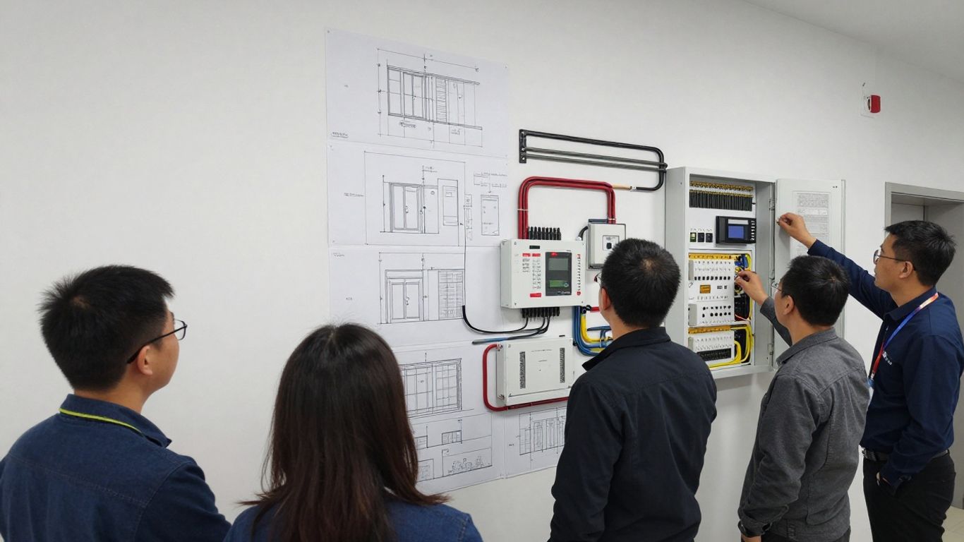
Create a door schedule that names every reader location, lock type, contact, request-to-exit device, and egress arrangement. Include whether a reader is inside, outside, or on both sides of the opening. Note cable distance and pathway conditions as well; a theoretically compatible device can still become a difficult installation if the route is congested or exposed to damaging conditions.
The schedule should also capture operational details. Identify which doors must remain available during a power interruption, which openings require monitored position status, and who will approve the final access behavior. These decisions belong with the responsible security and facilities stakeholders before wiring begins.
The enclosure decision is partly about present capacity and partly about the quality of future service work. A standard configuration may be appropriate where the door count, wiring volume, and power demand are limited. A large-can arrangement is more suitable when the project needs the documented expansion capacity, additional physical room, or dual internal power supplies.
The ACS6100 Large Can page describes a configuration supporting up to six expansion boards and up to 30 readers in total. Treat those values as configuration-specific design references. Confirm the final bill of materials and manufacturer documentation before ordering, especially when combining a main board, expansion boards, adapter plates, and power supplies.
Coordinate the controller location with the network team and the electrical contractor. Verify the intended Ethernet path, addressing process, cable pathway, grounding approach, and power availability before the enclosure is installed. Do not assume that a nearby network jack or receptacle is suitable without checking its ownership, labeling, and service plan.
The room itself matters too. Allow enough clearance to terminate cables, inspect indicators, replace components, and work safely. Keep the enclosure away from avoidable moisture, heat, vibration, and interference sources, and document any site condition that requires a project-specific mitigation.
Access rules should be defined before commissioning so the installer can test realistic scenarios. Map user groups to doors and schedules, then identify exceptions such as contractors, visitors, after-hours staff, and emergency access. Keep approval responsibility clear: technical staff can configure the system, but the organization’s designated owners should authorize who may enter where and when.
A clean permissions map also makes acceptance testing easier. Each test credential can be associated with an expected result, an expected event, and a responsible reviewer. That turns a vague request to “test access” into a repeatable test of the actual operating policy.
Hardware installation should preserve the design decisions made during planning. Mount the enclosure where it can be serviced, route field wiring cleanly, and keep power and communication conductors organized. Work from approved drawings and the equipment documentation rather than improvising terminal assignments. Clear identification saves time when several doors share a controller enclosure.
Use a solid mounting surface and provide the clearances required for the selected enclosure and power equipment. The controller should be accessible to authorized service personnel while remaining protected from casual interference. Before drilling, confirm the cable approach, door swing, nearby electrical equipment, and the route back to the network infrastructure.
Once the enclosure is positioned, check that the cover can be removed without disturbing field conductors. A serviceable installation is easier to inspect and less likely to suffer accidental disconnection during later work.
Follow the approved power and grounding method for the selected hardware. Keep power conductors distinct from low-voltage field wiring where the installation standard requires separation, and verify polarity before energizing the board. Label both ends of every conductor so a future technician can trace the circuit without reopening the entire design.
Do not energize an unfinished installation simply to see whether indicators illuminate. First inspect terminations, check for stray copper, verify the expected voltage, and confirm that the network and field wiring are not shorted. Controlled startup makes the first diagnostic result more meaningful.
An expansion board should be installed only after confirming that the enclosure, main board, power arrangement, and configuration support it. The B-ACS6100-DB expansion board is documented as providing two reader connections, eight inputs, and four outputs. Its reader inputs support RS-485 OSDP or Wiegand, and the published specification identifies 12 VDC at 500 mA peak with all relays engaged.
The board can replace ACS6000 series DBs when used with the B-ACS6100-ADPL adapter plate, according to the available product information. That compatibility detail is specific to the documented pairing. Record the installed board and adapter information in the as-built file so later service staff know exactly what was used.
Bring cables into the enclosure with enough slack for termination and service, but avoid large unsupported bundles that obstruct the board or power supply. Group conductors by door and identify each cable before landing it. Match the field label to the drawing, the terminal designation, and the software object name.
A short visual inspection should follow every completed termination. Check that shields, drains, commons, and polarity are handled consistently with the approved wiring method. Close the enclosure only after labels remain visible and the service path is still practical.
Field wiring is where a well-planned design becomes a functioning door. Reader communication, lock power, door-position monitoring, and request-to-exit inputs each have different operational consequences. Keep those circuits logically separated in the documentation even when they share an enclosure. The final test should prove each function independently before combined access scenarios are attempted.
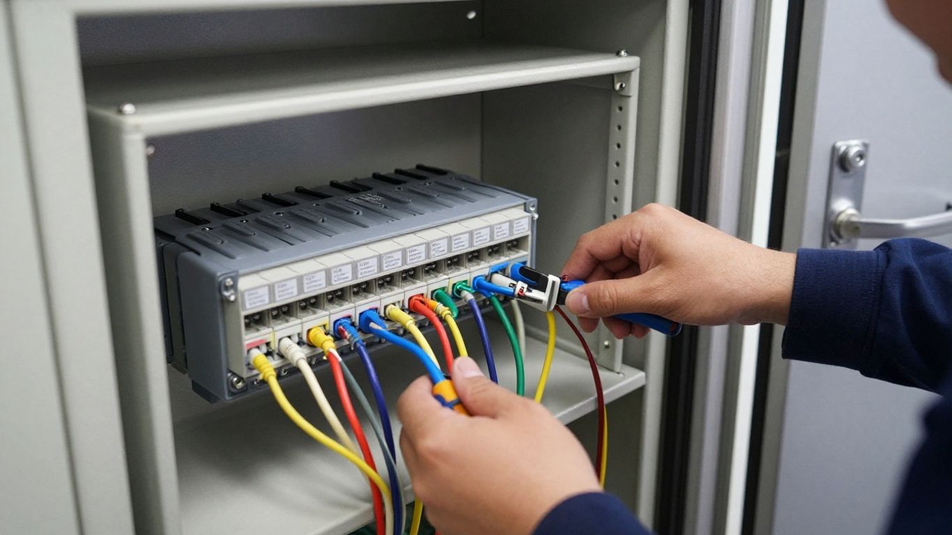
Start by confirming the reader interface selected for each door. The documented platform materials identify compatibility with Wiegand and OSDP readers, while the expansion board information identifies two reader inputs that can use either RS-485 OSDP or Wiegand. Match the actual reader model to the approved bill of materials and record its interface mode.
Reader cable routing deserves the same care as reader selection. Avoid unnecessary parallel runs with noisy power equipment, protect exposed pathways, and leave enough slack to replace a reader without cutting the cable. At the reader, verify conductors against the manufacturer’s terminal arrangement rather than relying on color alone.
OSDP uses an RS-485 communication path and requires disciplined wiring and addressing. Confirm the bus topology, polarity, termination approach, and reader address according to the reader and controller documentation. A reader that powers up but does not communicate is often a wiring, addressing, or configuration problem rather than a credential problem.
Record the address of every OSDP reader as it is installed. If several readers are on the same communication path, unique addressing is essential. Keep the record with the door schedule so software assignments and field labels can be compared during commissioning.
Use the video as a general visual aid, not as a substitute for the equipment documentation. The exact terminals, firmware behavior, and commissioning sequence should come from the approved technical materials for the installed components.
Wire the lock circuit and monitoring inputs according to the approved door diagram. A door contact reports position, while a request-to-exit device provides an input associated with authorized egress; the configuration should reflect how the opening is actually used. Check normally open and normally closed states at the device and in the software before testing a forced-door or held-open condition.
Lock power should be evaluated separately from controller power. Confirm voltage, current demand, suppression requirements, and the effect of any relay or power-transfer hardware. A lock that operates on the bench may behave differently once cable length, voltage drop, and simultaneous loads are introduced.
Fail-safe and fail-secure describe what the lock does when power is removed, but the right choice depends on life-safety requirements, local code, egress design, and the organization’s risk assessment. Do not select a behavior solely because it seems more secure. Coordinate the decision with the authority responsible for the door and emergency procedures.
Test the selected behavior under controlled conditions and document the result. Include normal access, denied access, power interruption where permitted, request-to-exit, and door-position events. The record should state what happened and who approved the behavior.
Configuration should mirror the physical installation rather than create a second, competing interpretation of it. Begin with the controller identity and site assignment, then map doors and readers before adding users and schedules. Use consistent names that facilities staff will recognize during an event review. A staged configuration is easier to validate than a large batch of unverified changes.
Prepare the controller record using the organization’s approved onboarding process. Confirm the site, network details, device identity, and administrative ownership before saving the configuration. If the controller does not appear as expected, resolve connectivity and identity issues before proceeding to door-level assignments.
Keep a change record for the initial setup. Note the date, installer, location, hardware configuration, and any temporary settings used during commissioning. This information can prevent confusion if another technician takes over before the project is accepted.
Create door objects that correspond directly to the door schedule. Assign the correct reader to each side, then map lock outputs, door-position inputs, request-to-exit inputs, and any expansion points. Review each assignment twice: once against the drawing and once by activating the physical device.
Avoid generic names such as “Door 1” when the site has several buildings or floors. A consistent naming convention improves event review and makes remote support more efficient. It also helps distinguish a software assignment issue from a field-wiring issue.
Build access levels around real job functions and operating hours. Keep the number of exceptions manageable, and document temporary access separately from permanent permissions. Before adding a large user population, test representative credentials for allowed, denied, scheduled, and expired conditions.
Permission changes should have an owner and an approval trail. Technical administrators can implement the requested rules, but the organization should retain responsibility for authorizing access. That division supports clearer audits and reduces accidental over-permissioning.
After configuration, verify that the controller communicates consistently and that events arrive with the expected door, reader, user, and event descriptions. Test from the management interface as well as at the physical opening. A successful command or visible status indicator alone does not prove that the complete event path is correct.
Review timestamps, labels, and event types during the test. If an event is missing or attached to the wrong door, stop and correct the mapping before adding more users. Early correction is much simpler than sorting through a large production log.
Commissioning should move from basic conditions to realistic operating scenarios. Check power and communication first, then test readers, lock outputs, contacts, request-to-exit devices, and management events. Record each result rather than relying on memory. This creates a baseline that is useful when a later fault appears.
Inspect the power supply, board indicators, network link, and controller status before presenting credentials. Confirm that measured voltage remains within the approved range under expected load. Check the physical network path, port status, and addressing information with the responsible IT team.
If the controller is offline, divide the problem into sections: power, local network, upstream connectivity, and management configuration. Changing several variables at once can hide the original cause. Restore one known-good condition at a time and document the result.
A reader fault may involve power, wiring, interface mode, addressing, or the reader itself. A lock fault may involve relay assignment, power delivery, suppression, or the lock hardware. A door-position fault may involve alignment, contact wiring, input state, or software mapping. Test these paths independently so a single symptom does not lead to an unfocused component swap.
Use a controlled credential and observe the complete sequence: credential presentation, reader response, access decision, relay action, physical lock response, and resulting door event. The first point where the expected sequence breaks usually narrows the investigation.
For OSDP issues, begin with the physical RS-485 path and verify polarity, continuity, topology, and termination as applicable. Then compare each reader’s address with the commissioning record and the configured reader object. Two devices sharing an address or a mismatch between field and software settings can prevent reliable communication.
Make one change at a time and retest. If a reader works when isolated but fails on the shared bus, investigate bus wiring and addressing rather than replacing the reader immediately. Keep the successful test state documented before reconnecting additional devices.
Acceptance testing should include normal users and boundary cases. Test credentials that should be granted, denied, limited by schedule, and affected by door status. Confirm that the resulting events are understandable to the people who will monitor and investigate them.
A concise test record can include the door, credential, expected result, observed result, event time, and reviewer. Resolve discrepancies before handover, and obtain sign-off from the appropriate security or facilities owner. Production users should not be the first group to discover a configuration error.
A completed installation needs an operating routine, not just a closeout date. Maintenance should cover hardware condition, connectivity, configuration, firmware, event records, and documentation. Establish responsibilities between the organization, its IT team, facilities staff, and service provider. That division is especially useful when a system spans multiple locations.
Schedule updates through a controlled change process. Review the applicable release information, confirm the current hardware and configuration, and choose a maintenance window that fits the site’s operating needs. Record the pre-change state and verify doors, readers, events, and administrative access after the change.
Do not combine unrelated changes during the same maintenance window unless the risk and rollback plan are clear. A focused update produces a cleaner result and makes troubleshooting more manageable if behavior changes afterward.
Routine log review can reveal repeated denied access, held-open doors, communication interruptions, or unusual administrative activity. Establish which events require immediate response and which belong in periodic reporting. Use consistent naming so a reviewer can understand the location without consulting several separate documents.
Controller health checks should include physical inspection where appropriate, network status, power condition, and recent event activity. Trends matter: a door that works most of the time but generates recurring communication or position alarms deserves attention before it becomes an outage.
Expansion should begin with a revised door schedule and capacity review. Confirm available enclosure space, power, network planning, reader interfaces, inputs, outputs, and service clearance before ordering additional hardware. The documented large-can configuration supports up to six expansion boards and up to 30 readers in total, but the installed configuration must be checked against those specifications.
When adding an expansion board, update both the physical drawings and the management configuration. Test the new door as a separate commissioning package, then verify that existing doors still operate correctly. This protects the live system from changes that appear isolated but affect shared power, wiring, or configuration.
Keep the as-built drawings, door schedule, reader addresses, hardware list, configuration notes, test results, and service contacts together. Include photographs of labeled terminations where policy permits. A future technician should be able to identify the equipment and understand the intended behavior without reconstructing the original project.
Set a review interval for documentation and access permissions. Changes in staffing, building use, network architecture, or emergency procedures can make an originally correct design incomplete. Predictable service depends on treating those records as active operational material rather than paperwork filed once at project close.
A well-executed access control installation connects thoughtful door planning with disciplined hardware work, accurate configuration, and documented testing. Organizations can reduce service friction by treating network, power, field devices, permissions, and maintenance records as one operating system. When the design must scale across locations, an experienced technology partner can help coordinate physical security, IT infrastructure, and ongoing support without losing sight of the site’s actual requirements.
Document each door, reader, lock, contact, request-to-exit device, cable route, power source, network path, access rule, and responsible approver. A complete door schedule gives installers and reviewers a shared reference.
Compare current door requirements with expected expansion, wiring volume, power needs, service clearance, and available mounting space. Select a configuration that supports the planned hardware without creating unnecessary capacity or restricting future work.
Wiegand is a commonly used reader interface, while OSDP uses RS-485 communication and supports addressed reader communication. The correct choice depends on the approved reader, controller, wiring design, and security requirements.
Test credential reads, access decisions, lock operation, door position, request-to-exit, denied access, scheduled access, and event reporting. Test each function separately before running combined scenarios.
Possible causes include incorrect wiring, polarity, interface selection, addressing, termination, configuration, or a faulty device. Isolate the reader and check one part of the communication path at a time.
Base the decision on life-safety requirements, local code, egress design, emergency procedures, and the organization’s risk assessment. Confirm the selected behavior with the responsible authority and test it under controlled conditions.
Maintain updated drawings, device addresses, hardware details, configuration notes, test results, firmware records, photographs where allowed, and service contacts. These records shorten diagnosis time and make expansions easier to manage.
Connect with us to explore our scalable solutions tailored to your unique needs and receive a personalized free quote.